So what is Digital Television. Part 3

Author: Bob Pank#
Published 1st September 2011
Last month Richard described moving forward from analogue to Digital video. This month he covers Gamma and conversion difference…
Gamma correction
An analogue factor to be considered in the handling of the video signal is the perception that the video display is accurately reproducing the brightness of each element of the scene. The Cathode Ray Tube (CRT) display is an inherently non-linear device and therefore, the amount of light output is a non-linear function of the voltage applied to the display. This function is called the gamma of the device. In order to produce a linear response, a correction factor must be applied within the TV System. Therefore, the RGB signals in the camera are gamma-corrected with the inverse function of the CRT. Gamma-corrected signals are denoted R', G', and B'; the prime mark (') indicating a correction factor has been applied to compensate for the transfer characteristics of the pickup and display devices. Although the prime mark may appear a bit cumbersome, and is sometimes incorrectly omitted, it will be used throughout this article for correlation with standards documents.
New LCD and Plasma display technologies are becoming more prevalent today, so one would think that gamma correction would not be needed in the future. However, the human visual response to luminance is also a power function; approximate intensity raised to the 1/3 power. For best contrast representation and signal to noise (S/N), video encoding uses this same power function. This is called conceptual coding.
Gamma correction is more than correction for CRT response
The gamma correction needed for the CRT is almost optimal for conceptual correction. For this reason, care should be taken when evaluating systems where correction factors have been applied within the devices for gamma correction.
Figure 4 shows the gamma correction as a power function of 0.45 as specified in ITU-R BT.709, a predominant standard for digital high-definition video. This gamma correction is applied at the camera to correct for nonlinearities at the CRT and provide conceptual coding. Nonlinearities in the CRT exist as a power function between 2.2 to 2.6, and most CRTs have a value of about 2.5. The resulting total system gamma is about 1.2, which is nearly ideal for typical viewing conditions. This response roughly corrects for human lightness perception, which in turn reduces the number of bits required when the video signal is digitized for transmission.
Conversion of R'G'B' into luma and colour-difference
Video components red, green, and blue are native to the camera pickup devices and are almost always used by operators in managing video colour. RGB, however, is not the most bandwidth-efficient method of conveying the image during video processing
because all three components must be equal bandwidth. Human vision is more sensitive to changes in luminance detail than to changes in colour, so we can improve bandwidth efficiency by deriving full bandwidth luma information and allot any remaining available bandwidth to colour-difference information.
Processing of the video signal components into luma and colour-difference values reduces the amount of information that must be conveyed. By having one full bandwidth luma channel (Y') represent the brightness and detail of the signal, the two colour-difference channels (R'-Y' and B'-Y') can be limited to about half the luma channel bandwidth and still provide sufficient colour information. This allows for a simple linear matrix to convert between R'G'B' and Y', R'-Y', B'-Y'. Bandwidth limiting of the colour-difference channels is done after the matrix. When the channels are restored to R'G'B' for display, brightness detail is R'G'B' for display, brightness detail is restored at full bandwidth and spatial colour detail is limited in an acceptable manner. The following paragraphs and tables discuss the conversion process for R'G'B' to Y', R'-Y', B'-Y' that takes place within encoders and decoders.
Gamma-corrected R'G'B' components are matrixed to create gamma-corrected component luma, designated Y', and two colour-difference components. The luma and colour-difference components are derived from R', G' and B' to the values shown in Table 1 (the unit of each coefficient is in volts).
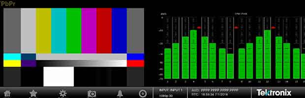
Table 1 shows the range of voltages for the conversion of R'G'B' to Y', (R'-Y'), (B'-Y'). The luma signal has a dynamic range of 0 to 700 mv. The colour-difference signals, R'-Y' and B'-Y', may have different dynamic ranges dependent on the scaling factors for conversion to various component formats. The analogue component format denoted by Y'P'bP'r is scaled so that both colour-difference values have a dynamic range of ±350 mv. This allows for simpler processing of the video signals. Analogue Y'P'bP'r values are offset to produce Y'C'bC'r values typically used within the digital standards. The resulting video components are a Y’ or luma channel similar to a monochrome video signal, and two colour-difference channels, C'b and C'r that convey chroma information with no brightness information, all suitably scaled for quantisation into digital data.
A number of other colour-difference formats are in use for various applications. In particular it is important to know that the coefficients currently in use for composite PAL, SECAM, and NTSC encoding are different.