
Don’t get me wrong - the advent of IP technology has done wonders for the broadcasting universe, especially here in Special Cams land where changing a setting could have involved a rather long walk and climb to a remote camera location! Nevertheless, this said, I still feel that serial communication is a huge contender - not only just in the realm of odd robotics systems, but also across broadcast in general.
In this article, I will walk through the very basics - introducing a few different types of serial and how they work.
So, very briefly, like all computer communications, serial is made up of binary - ones and zeros. For example, if a line had 5 volts on it, you could say it was ‘on’, thus has a value of one. If off (0 volts), you could say the value was zero. From this rapid turning off and on of a line, data can be sent - as is by Morse code. Each one of these zeros and one would be a ‘bit’. A collection of these bits would form a byte.
Framing a Byte
Now let us take a look at how collection of bits forms one byte, or one ‘instruction’:
Firstly, there will be a ‘Start Bit’ and one or two ‘Stop Bits’. These are sometimes referred to as sync bits and basically serve to tell the receiving machine where one message starts and ends.
Next, the important part - the data chunk. This is where your all important information hides and will be between 5 and 9 bits long. It is here were the command ‘start recording’ or ‘turn on tally’ could be coded for example.
The ‘Parity Bit’ follows that and is a rather cheap but effective form of error correction. Parity, in serial, will be one of three things- ‘Odd’, ‘Even’ or ‘None’. Of course, none would mean no parity - thus no error correction. Odd or Even however, would refer to the number of ‘Ones’ in the data chuck. So let’s say we had an 8-bit data chunk with the value of 00011111. The sum of the ‘ones’ is five, so if Odd parity was ‘true’ (or 1) - we would know the message was probably okay as the binary adds up as expected. If, however, even parity had been used and the bit still had the current value of ‘1’, as our binary sequence had an odd number, we would know the data was corrupt and to disregard it.
When reading through a user manual for equipment that has serial, it’ll have a number-letter-number combination such as 8N1, or 6E2, or 8O1. This would refer to the number of bits in the data chunk, whether or not it has odd, even or no parity - and how many stop bits will be sent. Useful information if you need to adapt the serial for use with external, third party systems.
You will also need to know the baud rate, often 9600 baud, which refers to the speed of the signal / how many 0s or 1s will be sent in a second. The higher the baud, the more data you can pass in a second, but also the higher the risk of lost packets.
RS 232
A known and loved serial format is RS232. RS232 could be performed on as few as two wires if one way commutation is acceptable (with the other wire being ground). Probably the most common deployment of RS232 is three wires, in which you would have a ground, a transmit (TX Line) and a receive wire (RX Line).
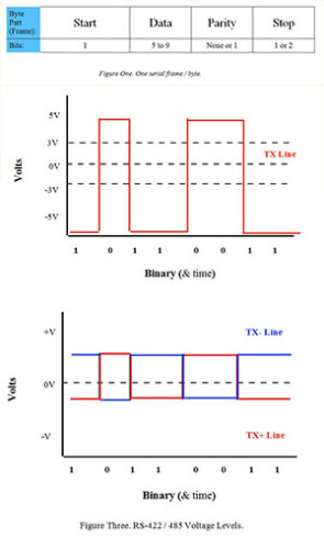
How you would define between a ‘one’ and ‘zero’ can be seen below in Figure Two.
In short, RS-232 will produce a ‘1’ whenever the voltage level is switched below the switching voltage of -3V and a ‘0’ when switched above 3v. Anything between 3v and -3V is not accepted as a valid switching voltage, and will return the previous binary figure if the limit is not met.
RS 422 / 485
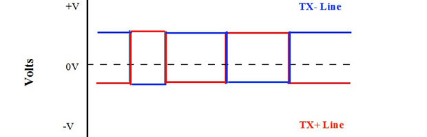
RS 422 / 485 is different to RS 232 is physical form. Unlike the three wires of RS 232, RS 422 and RS 485 feature five. A ground, a positive transmission line (TX+), a negative transmission line (TX-), a positive receive line (RX+) and a negative receive line (RX-). An example of this in action be seen below in Figure Three.
Unlike RS-232, RS-422 and RS-485 have separate lines to send not only a signal similar to RS232 in which a ‘low’ would return the value of ‘1’ (TX+) - but also another line (TX-) in which the opposite is true (high returns ‘1’). In doing this, for the signal to be valid - the negative signal should subtract and cancel out the positive signal. Doing so acts as a method of signal balancing, acting as error correction - thus enabling the signal to be sent over greater lengths before it degrades.